When creating and validating toolpaths in Mastercam, it’s important to understand not only where the tool will move, but also how the toolpath is being defined. That’s where the Display Graphical Elements feature comes in. Although often overlooked, these visual indicators can provide valuable insight into machining regions, linking parameters, avoidance areas, and other toolpath settings, helping programmers verify their intent before posting code or running a simulation.
Graphical elements are visual markers displayed in the graphics window that represent various aspects of a toolpath. They are not the actual tool motion; instead, they provide a visual reference for the parameters and geometry driving the operation. Depending on the toolpath, these elements may show machining boundaries, avoidance geometry, containment regions, linking planes, steep and shallow limits, workholding geometry, and more.
More Than Just Visual References
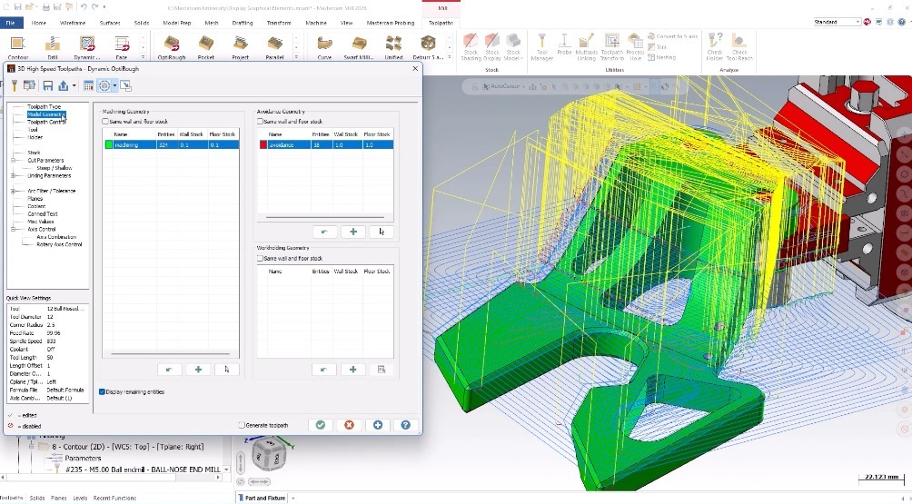
In some cases, graphical elements are purely informational. For example, they may simply highlight machining geometry or avoidance regions so you can quickly see what is being referenced by the toolpath. Other graphical elements are interactive, allowing users to make adjustments directly within the graphics window.
Linking parameters and steep/shallow limits are common examples. When displayed as movable planes, users can drag, reposition, or precisely adjust them using the on-screen ruler, mouse wheel, or direct numerical input. This makes it possible to fine-tune settings without navigating through multiple parameter pages. For programmers who frequently make iterative adjustments, this interactive functionality can be a significant time saver.
Accessing Display Graphical Elements
The Display Graphical Elements controls are located at the top of the Toolpath Parameters window for supported operations. Every compatible toolpath includes a dropdown menu that allows users to enable or disable graphical elements and access additional display options.
The specific options available vary based on whether the operation is a 2D, 3D, holemaking, or multiaxis toolpath, but the goal remains the same: providing a clearer understanding of how a toolpath is configured.
Key Display Options Explained
One of the most useful settings is Display Only Elements on Current Page, which is enabled by default. When active, Mastercam only displays graphical elements associated with the parameter page currently being edited. This helps reduce visual clutter and keeps the focus on the settings you’re actively working with. Disabling the option causes all graphical elements associated with the toolpath to display at once, which can be useful for seeing the complete picture but may become overwhelming on more complex operations.
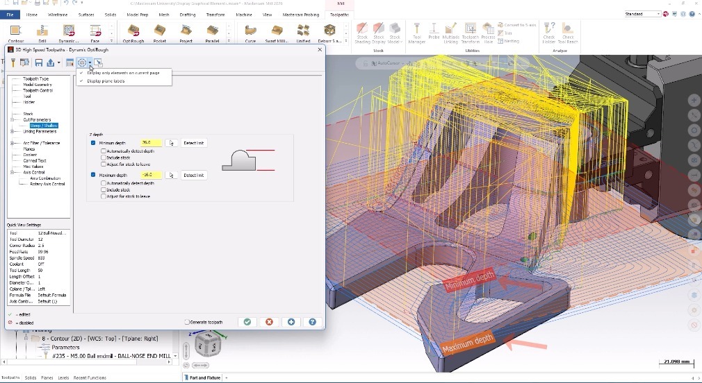
Another common option is Display Plane Labels. When enabled, plane names are shown directly in the graphics window, making it easier to identify and verify plane assignments. When disabled, planes are represented by simple colored markers instead.
For certain 2D toolpaths, users will also find a Simplified Plane Display option. This setting is designed to reduce screen clutter when machining multiple regions within a single operation. Rather than displaying plane markers for every machining area, Mastercam displays markers for only one area. While this creates a cleaner display, programmers should use caution. If different machining regions use incremental linking parameters and are located at different depths, simplified plane display can obscure those differences and make it more difficult to understand how linking values relate to each feature.
Understanding Colors and Visual Indicators
Not all graphical elements can be customized. Plane markers and linking parameter indicators use fixed colors to maintain consistency across toolpaths. However, geometry selections such as surfaces, solid faces, meshes, curves, and points may display color-coded indicators that can help distinguish their purpose within the operation.
These visual cues become especially useful in more complex parts where multiple geometry types are being used to drive a single toolpath.
Graphical Elements in 2D Toolpaths
The types of graphical elements displayed vary significantly depending on the toolpath category. In 2D toolpaths, programmers can visualize chained geometry, machining and avoidance regions, containment boundaries, air regions, entry chains, and various linking parameters such as clearance, retract, feed plane, top of stock, depth, and breakthrough.
These visual aids are particularly useful when verifying cutting boundaries and depth relationships before generating tool motion. Automatic regions also display graphically, adopting the color of the region type that Mastercam determines each selected area represents.
How Holemaking Toolpaths Differ
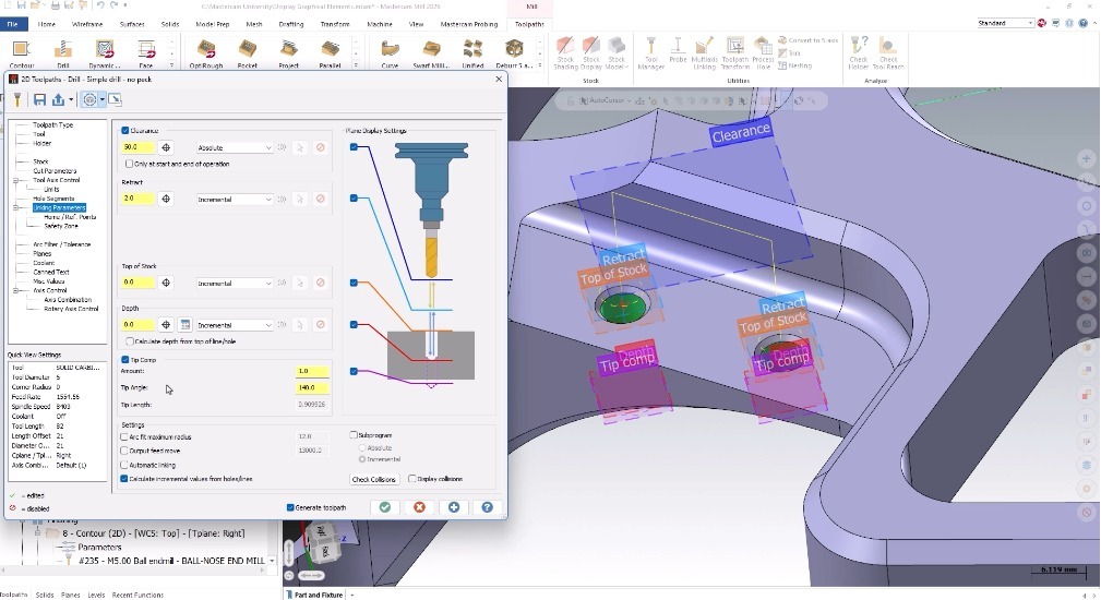
Holemaking operations offer a more streamlined implementation. The focus is primarily on depth and positioning verification, with plane-related information serving as the primary graphical reference. In these operations, tip compensation is displayed instead of breakthrough on the linking parameters page.
Users may also notice color changes on selected hole geometry; however, this behavior is separate from the graphical elements feature and remains visible whenever active hole geometry is selected.
Visual Verification for 3D Toolpaths
For 3D toolpaths, graphical elements can display machining geometry, avoidance geometry, workholding geometry, control boundaries, curves, points, and steep/shallow planes. Depending on the operation, users may also see approximate start points for multiple machining regions and graphical representations of clearance values.
These visual indicators provide another layer of validation, helping programmers confirm how the toolpath interacts with the model before machining begins.
Multiaxis Toolpath Support
Multiaxis toolpaths provide perhaps the most varied implementation. The graphical elements displayed depend heavily on the selected toolpath strategy but generally include machining geometry, avoidance geometry, and cut pattern information.
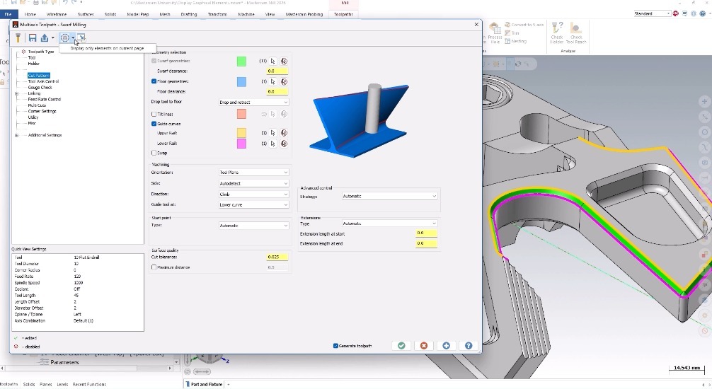
It is important to note that not every multiaxis toolpath supports graphical elements. Legacy toolpaths such as 5-Axis Curve, Multi-Surface, and Flowline do not include this functionality, so the Display Graphical Elements option will not appear in their parameter windows.
A Feature Beyond Milling
Although graphical elements are most commonly associated with Mill and Router toolpaths, they can also be found in the Lathe Drill toolpath within the General Turning tab. This extends the benefits of visual verification into turning applications as well.
Why Graphical Elements Matter
Display Graphical Elements is much more than a visual enhancement. It is a practical verification tool that helps programmers better understand their toolpaths, identify potential issues, and validate critical settings before machining. By converting parameter values into visual references, Mastercam makes it easier to confirm machining intent, reduce programming errors, and work more confidently.
For new users, graphical elements can help explain what different parameters actually control. For experienced programmers, they provide a fast and effective way to verify settings without digging through multiple pages of parameters.
▶ Watch the full Show Me video on myMastercam and discover how graphical elements can improve your daily programming workflow.
Learn about even more features that can help you personally with Mastercam Product Trainings, which offer hands‑on guidance and best practices to help you maximize your results.