When you are programming a machine that supports both turning and milling but is not recognized as a Mill-Turn machine in Mastercam, you may run into a frustrating issue: your 3D turning tool does not appear in the correct position during simulation.
It is a small detail, but it matters. Accurate visualization is essential for validating your setup, preventing collisions, and doing your best work with confidence. The good news? There is a simple, reliable way to correct this tool position using the tool definition already inside Mastercam.
Let’s walk through how it works.
Understanding Why Tools Misalign in Simulation
In the example shown in our Show Me video, the machine is defined as a lathe, so you can program turning operations. However, because it is not listed as a “Mill‑Turn” machine in the Machine Type dropdown, Mastercam does not use the Tool Setup Manager to determine how tools load into the spindle.
That means when you send a turning operation to simulation, Mastercam applies a default attachment point, and that default does not always match how the simulation environment expects a tool to be positioned. The result: a tool that loads off-center or out of alignment.
This misalignment doesn’t affect toolpath calculation, but it can misrepresent what is actually happening on the machine. And for many programmers, simulation is where confidence is built.
The Fix: Use the Manufacturer Code Field to Shift the Tool in Simulation
To correct the tool position, you simply need to tell Mastercam how to offset the tool in 3D space. This is done by entering a set of positional values (X, Y, Z, and L) into the Manufacturer Code field of the tool definition.
Here is how to find and enter those offsets:
Step 1: Edit your tool definition
- Open the Lathe Tool Manager.
- Select the tool and choose Edit Tool.
- Go to the Cutting Definition page.
- Locate the Manufacturer code field.
This is the field Mastercam uses to apply positional adjustments for tools in simulation.
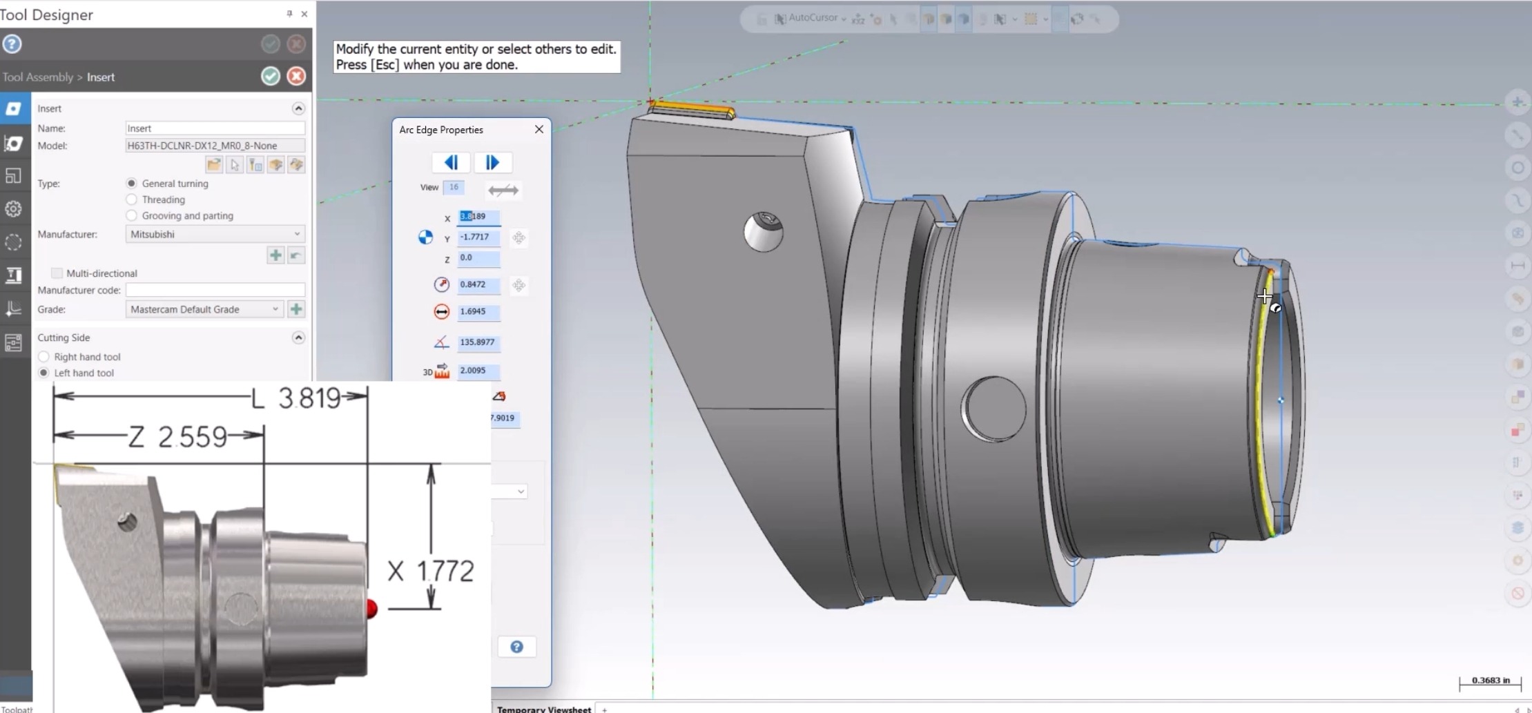
Step 2: Determine the correct X, Y, Z, and L offsets
To find the correct values for the Manufacturer code field, you will use Mastercam’s Analyze Entity tool. These offsets are based on the image Mastercam uses internally for interpreting lathe tool positioning.
A key thing to remember: The axis labels in the Analyze dialog don’t directly match the axis labels in the image.
Here is how they translate:
From Top View:
- Analyze X → Image Z
- Analyze Y → Image X
- Analyze X at the back of the tool → Image L
From Front View:
- Any centerline shift from the insert tip to the center of the tool body becomes the Y value in the Manufacturer code.
If your part file is inch-based, values will appear in inches. If it is metric, you will see millimeters.
Step 3: Enter the values into the Manufacturer code field
Once you have all four values (X, Y, Z, L), enter them in this format: X[value]Y[value]Z[value]L[value]
This string tells Mastercam exactly how to offset the tool, so it loads in the correct position during machine simulation. Save the tool, regenerate your operation, and open Simulation again. You will then see the tool correctly aligned in the spindle.
Working with Complex Tool Assemblies
This method also works beautifully for multi-component assemblies.
For example, if you have:
- A stick tool
- Held in a locator block
- With that block defined as an adapter
You can gather values the same way: from the tip of the tool back to the assembly’s gauge line center. Since the geometry is larger, the values will naturally be larger, but the process is identical.
What’s even better: Once you store this information in the tool definition, every future program using that tool will load correctly. No extra setup. No repetitive adjustments. Just consistent, reliable simulation.
Troubleshooting: What if the Tool Still Does Not Move?
If the tool does not change position relative to the spindle after entering the Manufacturer Code offsets, your simulation package may not yet support this functionality.
In that case, contact your Mastercam representative. They can update your machine simulation environment to ensure these offsets work as intended.
A Small Adjustment with a Big Impact
Hybrid turning/milling machines give you incredible versatility, and your simulation should reflect that accuracy. Applying the Manufacturer Code offset ensures your tools appear exactly where they should, giving you a trustworthy, realistic view of your operations.
This quick adjustment brings clarity, reinforces confidence, and keeps your workflow moving without unnecessary guesswork.
For more information, be sure to watch the full Show Me Video on mymastercam. If you want help applying this to your own setup, or if you’re working with a more custom machine environment, your Mastercam representative is always ready to help.
You can also take your expertise even further with Mastercam Product Trainings, which offer hands‑on guidance and best practices to help you maximize your results.